When it comes to dust collection, it is essential to understand the importance of conveying velocities and their impact on the proper design of a system. Moving air through ducts too slowly or too quickly can have significant consequences that are equally problematic. The optimum conveying velocity may vary depending on the type of dust in the application, but there are several design practices and devices you can use to select and maintain the optimum air volume and resulting velocity.
You may also be interested in our Dust Collector Maintenance page
CONSULT THE INDUSTRIAL VENTILATION MANUAL
The Industrial Ventilation Manual1 from ACGIH is the industry-recognized resource for determining recommended design practices in industrial ventilation, and it includes guidance on carrying (or conveying) velocities. In general, the heavier a particulate the higher the conveying velocity required to keep it moving through a duct. Lighter particulate can be kept in motion with lower conveying velocities, which may help reduce your operating costs.
PROBLEMS CAUSED BY INAPPROPRIATE CONVEYING VELOCITIES
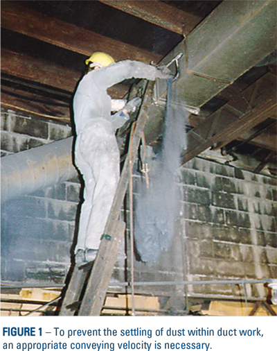
 Whether you are dealing with light or heavy particulate, you must design the ducts to prevent material from settling out of the air steam inside the duct. (Figure 1) As an example, lead dust, which is relatively heavy, typically requires a minimum conveying velocity of 4,500 feet per minute, whereas weld fume, which is much lighter, may require 2,000 – 2,500 feet per minute. When conveying velocities are not sufficient to keep the material moving through the duct, the potential exists for the dust to dropout and settle in the duct. If the duct does not remain free of debris, the duct or its supports may eventually fail due to the additional loads, or the accumulation of material may create other concerns such as combustibility or corrosion.
Another side effect of dust accumulation inside the duct is the reduction in duct cross sectional area. Because the design air volume is now trying to be pulled through a smaller cross sectional area, the air velocity would have to increase through that section of duct to maintain the design flow. If the fan has the static capacity to overcome the additional energy restriction related to a higher velocity, the section of the duct may experience increased abrasions as a result of the higher velocities. More typically, the fan will not have sufficient static capacity, and, as a consequence, the total air volume will drop resulting in reduced capture performance at the hood and an overall reduction in the system’s performance.
Maintaining sufficient velocities to prevent dust from dropping in the duct is important, but there are negative impacts resulting from excessive duct velocities. Abrasive dusts will wear away at duct material, eventually requiring replacement, and excessive velocities can accelerate that wear. Furthermore, it requires much more energy to move air at a higher velocity. Buying a fan with more static capacity will increase the cost of initial capital and will increase energy costs every day the fan is running. Therefore, keeping the design air volume moving at just the right conveying velocity is a critical consideration in system design.
ADVANTAGES TO PROPERLY CONTROLLING CONVEYING VELOCITIES
There are a several methods for controlling conveying velocities – the first being good initial duct design. The duct selection process should ensure proper conveying velocity based on the design air volume.
 One of the challenges in practical applications is that systems may not operate at their ideal design air volume at all times. Air volume through the system may be fairly dynamic. As an example, clean filter media will eventually start to load with dust. The increased resistance across the dirty filters can then reduce the air volume delivered by the fan, resulting in lower air volume through the duct system and the hoods. This reduction in air volume is often corrected by opening an outlet damper on the fan to compensate for the resistance developed as the filters build up a dust cake. However, the damper method is only effective if employees monitor the situation. A common flaw in this approach is not remembering to close the damper back down to return to design flow when installing new filters, which no longer have the resistance from a dust build-up. Often the damper is left in the fully open position when new filters are installed and the system runs at an increased air volume. This error can lead to excessive air volume at the hoods, which may create problems such as collecting unwanted product. It may also increase abrasion rates in the duct system, as well as dramatically reduce the effective life of the filters, requiring more frequent replacement and servicing.
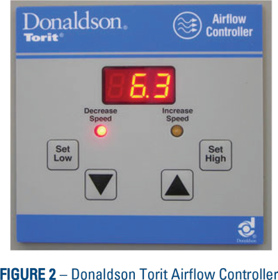
A more reliable way to maintain design air volume in the system is by using an Airflow Controller. (Figure 2) This device monitors the static pressure in the dust system just ahead of the collector and constantly sends feedback to a variable frequency drive on the fan to adjust fan speed.
This adjustment to fan speed can then maintain consistent air volume through the duct system, and, because air volume and duct velocity are proportional, the conveying velocity in the ducts remains stable and the system operates consistently at design conditions, ensuring effective dust collection.
COST SAVINGS TO BE HAD
It is critical to understand conveying velocities in your dust collection duct system. Excessively low or high conveying velocities can each cause undesirable consequences from dust falling out in the duct to excessive duct abrasion, and there are economical advantages to optimizing the air volume in the system to ensure the desired conveying velocity. You can limit capital costs on the system’s fan, and you can reduce the everyday operating expense for that fan by operating at appropriate and optimized conveying velocities. Additional savings may be realized as you will also reduce the problems related to duct abrasion and/or undesirable dust fallout in your ducts.
